Understanding the Functions of Manifold Valves in Hydraulic Systems
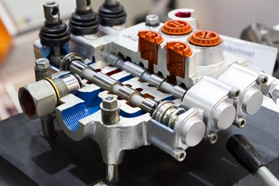
A hydraulic manifold is simply a block of metal with pressure inlets, service ports and low pressure outlets, onto which or into which other valves are attached.
Knowing how each component works and interacts is essential to understanding hydraulic systems. A hydraulic circuit consists of motors, pumps, valves, and many other parts. The traditional type of valve connects via hose or steel pipe to other valves and the other components in the circuit. This results in lots of connections and therefore greater potential for leaks. Combining a number of valves into a single valve manifold is what the printed circuit board is to electronics. Incorporating all of the valves required into one manifold block using cartridge valves reduces the space required and potential for leaks.
 The use of manifold valves has been evolutionary with the most basic being monoblock directional control valves incorporating inlet relief valves followed by anti-cavitation and service line relief valves. Where quantity makes it worth it these valves can have extra check valves, pressure reducing, counterbalance and other valves built into them so that when delivered to an OEM production line there is little setting up of the valves required as they have all been preset by the valve manufacturer to the OEM’s requirements.
The Cetop system uses a manifold system that at its simplest stacks single valves in their own manifolds onto a base manifold, it reduces the need for connecting pipework but is not necessarily very compact. With the more sophisticated hydraulic manifold valves porting apertures are located throughout both for connection to the rest of the circuit and the cartridge cavities into which the control valves will be fitted. The compact design is one of the benefits of a valve manifold. Aside from saving space, it can also reduce equipment costs. The advantages of incorporating hydraulic valves into manifolds are:
- Provide shorter flow pathways: This reduces pressure drop and fluctuations in heat; energy efficiency is improved as well.
- Reduces the number of connections: With fewer hose and fluid connections, installation costs, wear and tear, and the chances of oil leaks are reduced.
- Integrates universal porting: The manifold is compatible with a wide range of components; the overall layout of the system is also improved.
Utilising cartridge valves in a valve manifold simplifies the design of just about any
hydraulic system. Surface-mounted or cartridge-style valves can be integrated, as well as pressure and flow controls. Designs that thread into cavities within the manifold minimize the number of threaded or flanged connections, reduce system weight, and reduce installation and OEM assembly time.
However, as with everything with greater circuit complexity comes greater machining complexity and therefore one is reliant on machining accuracy and material integrity to prevent leaks. When trouble shooting circuit problems, diagnosis can become very difficult in the case of complex hydraulic manifolds. in many cases the only option is to start by swapping over the valves from the original manifold to a new one to eradicate the chance of the problem being an internal leak between cavities.
How Does a Manifold Valve Work?
In many ways, the function of a hydraulic system is similar to an electric circuit. Both require working interconnections linked directly to control elements. Valves serve the purpose that switches and transistors do in an electronic circuit. They control fluid pressure and flow and as we know cartridge valves built into manifolds are very efficient at this capability.
Types of Manifold Valves

For a better overview of
hydraulic valves explained, here is a look at the different types. You can find two-, three-, and five-way valves, but the major types of manifolds to look for include:
- : Custom built manifolds designed specifically for an application. They can’t be easily modified later, but these manifolds have connections in locations most suited for the application they’re intended for. Fluid paths are machined, milled or cast through the metal layers. Along with solid metal end pieces, the entire assembly is normally tied together normally using threaded rod. Laminar manifolds can handle pressures up to 10,000 psi and any flow rate can be accommodated with little pressure drop by increasing the size of the internal cavities and connections relative to oil flow.
- Drilled metal-block: Made from plates, blocks or bars of metal (steel, aluminum, or cast iron), drilled metal-block manifolds are machined to create flow passages and circuit paths between cartridge valve cavities. All passages are straight unless starting with a casting that has some passages already cast into it, but valves can be configured as needed, allowing these manifolds to be easily customized.
- : Modular manifold systems are easy to modify and include modular aluminum, cast iron, or steel blocks. These can be configured as needed, so you can design and build your own multi-function valve using a modular approach. Modular systems can, as in the case of the Cetop system, be stacked or assembled horizontally. They’re usually single function valve modules / slices with interface seals that fit one after each other depending upon the valve functions required for that part of the system / circuit..
Other Aspects of Manifold Valve Function and Design
Manifold valves; if incorporating electrical solenoid control valves can be operated electronically either utilizing simple on off switches or more sophisticated joystick or potentiometer control.. These connections can be wires that run from the valve to the electrical power source, control panel or operator’s seat area in the case of mobile plant. The valves may in some cases be attached to radio receivers for wireless operation or PCBs for pre-programmed operation.
Designing a hydraulic manifold can be accomplished using computer-aided design software and CNC technology. It’s important to consider the many design requirements: fluid type, seal materials, operating temperatures, pressure, flow conditions, and voltage requirements. All influence the type of manifold you use and how it is configured, port types, sizes, and locations, as well as mounting type need to be considered as well.
A manifold-block assembly may be secured with tie rods and nuts, while others use external flanges or socket-headed studs. Fluid channels can use O-rings and or bonded seals for sealing, while the location of pump and tank connections may vary with the type of manifold system. External porting can be placed at the optimal and, in some cases, one inlet can be used for multiple circuits. The hydraulic manifold, therefore, reduces the distance for fluid to flow from pressure source to control point.

Common materials for manifold valves include aluminium, which typically suits applications requiring operating pressures below 210 bar (3,000 psi). For higher pressures in the 210bar to 420 bar (3,000 to 6,000 psi) range, steel can be used. Less common materials, including alternative aluminum alloys, titanium or Inconel may be used, especially if there are considerations such as corrosive fluids, extra high pressures or environmental requirements that preclude the use of steel or aluminium.
Order Valve Manifolds and Hydraulic Components from White House Products, Ltd.
Valve manifolds have a high degree of design flexibility. You can order specific valves, sensors, accumulators, filtration elements, and more from White House Products, Ltd., one of the most trusted
hydraulic pump suppliers on the market. We can help accommodate just about any hydraulic manifold valve application. Browse our catalog to learn more about our hydraulic pumps, motors, and other products from leading manufacturers, or give us a call at +44 (0) 1475 742500 for assistance by a knowledgeable representative.
Back to blog posts